

OEM Expansion Shell Bolt: Key Factors for Reliable Fastening in Industrial Applications
2026-10-24
A single loose bolt can bring a production line to a halt—or worse, compromise safety. Yet in OEM applications, expansion shell bolts are frequently treated as commodity parts, selected on price alone. That shortcut rarely survives contact with real-world vibration, thermal cycling, and uneven loads. Here, we explore what separates a dependable expansion shell bolt from a potential failure point, and how Supreme Machinery helps OEMs eliminate guesswork.
The Overlooked Role of Base Metal Hardness
Base metal hardness rarely gets the attention it deserves. Most welding procedures zero in on filler metal strength, preheat temperature, or heat input, while hardness is treated like an afterthought. Yet that value tells you how the parent material will react to a sudden thermal cycle. A steel with high hardness—say, 350 HB or above—often has a martensitic or heavily tempered microstructure with limited ductility. Weld it with the same cooling rate you'd use on mild steel, and the heat-affected zone can crack before the weld even cools to room temperature. That isn't a filler metal problem; it's a mismatch between procedure and base metal reality.
Hardness also shapes how residual stress builds up. Softer base metals yield locally when the weld shrinks, which redistributes stress and lowers the peak tensile load. Harder grades don't give way as easily, so the stress stays concentrated near the toe or root of the weld. Months later, under a light service load or even just from hydrogen already trapped in the joint, a crack appears where none was visible after inspection. This delayed failure often gets blamed on welding technique, but the real trigger was a base metal that couldn't accommodate the same strain a lower-hardness alloy would have absorbed without complaint.
A practical check is to measure hardness before writing the WPS. Don't rely on the mill certificate or a generic grouping. Drill a small test coupon or use a portable hardness tester on the actual plate or pipe you're about to join. If the numbers come back higher than expected, increase preheat, slow the cooling rate with insulation, or add a post-weld hydrogen bake. The goal isn't to lower the base metal's hardness permanently—that could ruin its designed properties—but to give the joint a cooling path that respects what the material already is. In short, treat hardness as a signal rather than a side note, and you'll stop chasing cracks that have nothing to do with the weld itself.
Hole Prep Errors That Quietly Reduce Hold
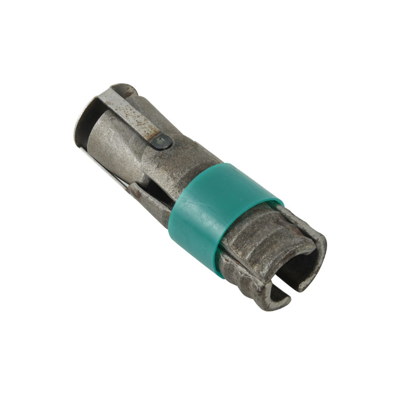
Dust left in a fresh hole is one of the biggest silent killers of screw hold. After drilling, the flutes bring up fine particles that sit between the threads and the wall. When you drive a screw into that debris, the threads can't bite cleanly; they compress the dust into a slick layer that lets the fastener back out under vibration. Blow out the hole or use a narrow brush before driving, and you'll feel the difference in torque immediately.
Pilot hole size gets blamed for stripping, but depth is just as critical. A hole that stops short pushes the screw tip against solid wood, which either snaps the screw or leaves it standing proud. Too deep, and you've removed the material that was supposed to clamp the threads. Mark your bit with tape or a depth collar, and test on scrap of the same density first. Hard maple needs a few thousandths more clearance than pine, and ignoring that leads to cracked boards and weak joints.
The entry edge is another place where hold quietly erodes. Without a slight countersink or chamfer, the screw head catches on the surface fibers, lifting them and creating a small gap between the head and the material. That gap means less clamping pressure across the joint, even if the screw feels tight. A quick twist with a countersink bit—just enough to break the edge—lets the head seat flat and keeps the pull-out strength where it belongs.
Getting Torque Right Without Damaging the Shell
Most cracked shells come from one simple mistake: trusting feel over numbers. If the fastener has a specified torque, use a calibrated torque wrench and work in small increments, alternating between screws in a cross pattern. This spreads clamping force evenly so no single point takes too much stress. For plastic or thin metal shells, even a few extra Newton-meters can leave hairline fractures that only show up later.
When no torque spec is available, stop tightening as soon as the screw head sits flush with the surface. Back off a quarter turn if you feel sudden resistance or hear a creak. Using the correct bit size and applying steady downward pressure prevents the driver from slipping and gouging the surrounding material. A drop of medium-strength thread locker can keep properly seated screws from loosening, so you don't have to rely on excessive torque for security.
If you are working with an older shell that has already seen some stress, inspect the screw bosses before reassembly. A small crack near a boss can spread quickly under load. Reinforcing the area with a washer or a thin metal insert often allows you to reach the needed torque without crushing the shell.
What Happens When the Anchor Meets a Crack
When you slot a cam or nut into a crack, the forces aren't as straightforward as they look. The rock might flex or crumble, especially if the crack is flaring or has loose crystals. The placement can feel solid at first, but under a sudden load it shifts, and the anchor's contact points start working against the crack's irregular surface. That's when you hear the quiet scrape of metal on stone, and you realize the real test isn't the gear itself but how well it matches the crack's geometry.
If the crack is wide or shallow, the anchor may only catch on a small lip. A fall then turns that lip into a fulcrum, and the anchor rotates slightly, concentrating stress on one edge of the rock. In softer stone like sandstone or limestone, that edge can blow out, leaving the anchor useless. Even in granite, a poorly seated anchor can walk deeper into the crack as it vibrates, changing the angle of pull and causing the rope to run over a sharp edge. The result is rarely a clean failure; it's usually a slow, grinding shift that tells you the placement was never as good as it looked.
Why Some Bolts Back Out Under Vibration
Threaded fasteners rely on friction between mating threads and under the bolt head to stay tight. When a joint experiences vibration, especially transverse motion perpendicular to the bolt axis, the contact surfaces can slip microscopically. This slip momentarily reduces the friction that holds the bolt in place, allowing the nut or bolt to rotate slightly. Repeated cycles of vibration produce a gradual loosening effect, and the fastener backs out even if the external load never exceeds the bolt’s strength.
Another factor is loss of preload. A properly torqued bolt stretches slightly, creating clamping force that locks the threads together. Vibration can cause embedment or local yielding at the contact surfaces, which releases some of that stretch. Once preload drops below a critical level, the joint becomes more susceptible to relative motion, and the loosening process accelerates. This is why designs with short grip lengths or soft joint materials are more prone to backing out.
In practice, the most damaging vibration is often perpendicular to the fastener axis, because it forces the threads to slide sideways relative to one another. Locking features such as nylon inserts, deformed threads, or prevailing torque nuts work by increasing the friction that must be overcome before rotation can begin, but they cannot prevent preload loss if the joint geometry is poor. The key is maintaining enough clamp force so that the friction demand never drops below the threshold needed to resist vibration-induced slip.
Geometry Mismatches You Didn’t Know to Check
Many people assume that if two models line up visually, everything is fine. But “close enough” hides some of the most expensive rework. A steel beam that passes through a duct by half an inch won’t show up in a standard clash report if the tolerance is set too loose.
One often-overlooked mismatch is between architectural grids and structural grids. When a project uses a shared coordinate system, a tiny rotation error in one file can shift every subsequent element. Another is the gap between top-of-steel and bottom-of-deck—if the deck profile changes but the steel elevation doesn’t, you get a floor that slopes where it shouldn’t.
To catch these, I’ve found it useful to turn off all but a few critical reference planes and zoom into the joints. The mismatches are rarely dramatic; they hide in the tenths of an inch. If you’re not seeing them, try overlaying the models in a section view and toggling one discipline at a time.
FAQ
An OEM expansion shell bolt is matched to the specific base material and load requirements of the original equipment, so the sleeve geometry, thread tolerance, and finish are tuned for repeatable installation rather than being a one-size-fits-all fastener.
Solid concrete and grouted masonry generally allow the expansion leaves to bite evenly. Avoid hollow block or severely cracked concrete unless the manufacturer has verified the specific bolt for those conditions, otherwise the shell may not expand symmetrically.
Torque controls how much the cone is drawn into the expansion sleeve, which sets the initial preload. Too little torque leaves the anchor loose and vulnerable to vibration; too much can strip threads or crack the base material, so staying within the OEM torque range is critical.
If the hole is too shallow, the expansion sleeve may not fully engage, reducing contact area and load capacity. If it is too deep, the bolt may bottom out before the cone seats properly, giving a false sense of tightness. A depth gauge should be used for every hole.
Reuse is usually not recommended because the sleeve deforms during expansion, and the cone may have worn threads. Even if the bolt looks intact, the expansion mechanism may not achieve the same holding power the second time.
In chemical plants, wastewater facilities, or coastal settings, a zinc-plated shell bolt can fail well before its load rating is reached. Hot-dip galvanizing or stainless steel should be chosen based on the specific corrosive agents, not just the general environment.
Use a calibrated torque wrench and follow the OEM's torque sequence. After tightening, you can mark the nut and base material with a paint line, then check periodically for movement. A sudden drop in torque during recheck often indicates base material cracking or thread relaxation.
When anchors are placed too close together, the expansion forces overlap in the base material and can create a cone-shaped failure zone. Minimum spacing preserves the integrity of the surrounding material so each bolt carries its share of the load independently.
Conclusion
The reliability of an OEM expansion shell bolt in industrial settings hinges on factors that are often overlooked during design and installation. Base metal hardness, for example, governs how the expansion mechanism loads the surrounding material. In softer substrates, the shell can compress the base metal without generating enough friction to hold; in harder materials, the same torque may not allow the shell to seat properly, leaving the anchor loose. Hole preparation errors compound these problems: an oversized hole, rough edges, or leftover drilling debris can silently reduce effective contact area and lower pull-out resistance, even when the bolt appears tight. Achieving correct torque adds another layer—too little and the expansion doesn't fully engage, too much and the shell neck can yield or the base material can crack around the hole.
Once in service, the situation gets harder to predict. When an anchor is set close to a crack or edge, stress paths shift, and the load can concentrate in ways that standard pull-out tests don't capture. Vibration is another common enemy: cyclic loading relaxes the contact pressure, and bolts that were initially torqued to specification can gradually back out unless the expansion profile and mating geometry are carefully matched. Unsuspected geometry mismatches—thread form, cone angle, sleeve length, or even the chamfer on the hole—can turn a well-specified fastener into a weak link. Reliable fastening with these bolts is not about selecting a higher strength grade, but about aligning base metal behavior, hole quality, torque application, and geometric compatibility from the first installation step.
Contact Us
Contact Person: Paul
Email: [email protected]
Tel/WhatsApp: 8615067447509
Website: https://www.spironcasting.com