

Air Conditioner Factory Production and How Modern Cooling Units Are Assembled
2026-11-16
Ever wonder what happens behind the sealed doors of an air conditioner factory before a single cool breeze reaches your room? The journey from raw sheet metal, copper tubing, and refrigerant lines to a finished cooling unit is more intricate than most people imagine. Modern assembly lines now blend robotic precision with hands-on inspection, balancing speed against the kind of quality checks that keep compressors humming for years. In this post, we walk through the key stages of production, from coil forming and brazing to vacuum charging and final performance testing. Along the way, we will also look at how manufacturers like PAULAIR approach assembly differently, focusing on the small details that separate a forgettable unit from one that quietly does its job season after season.
From Raw Aluminum and Copper to the Factory Floor
Aluminum starts as bauxite that gets crushed, washed, and refined into alumina before it spends hours inside reduction cells. The metal leaves the smelter as ingots or continuous coil, usually with faint oxide staining and trace marks from the casting line. Once it reaches a plant, it is cut, bent, punched, and welded into frames, enclosures, brackets, and heat sinks. On the floor it rarely looks pristine, and that is normal; the slight surface variation comes from mill speed, alloy temper, and handling.
Copper takes a different path. Sulfide or oxide ores go through flotation, smelting, and electrorefining until they become cathode plates. From there the copper is drawn into wire, rolled into sheet, or formed into tube and busbar. A factory may receive it as bright rod, heavy plate, or thin strip, then turn it into motor windings, switchgear, connectors, or refrigerant lines. Its softness is useful up to a point, but it also means tooling pressure and bend radii have to be watched more closely than with steel.
At the factory the two metals meet in ways that rarely get noticed. Aluminum carries the structure; copper handles the current. A single machine can contain both within a few centimeters, one part chosen for weight, the other for conductivity. Workers adjust blade clearance, feed speed, and hold-down force based on the alloy batch, because even the same grade can arrive with different springback or burr behavior. Raw ore is far away by then, but the decisions made at the smelter and mill still show up at the press brake, the CNC table, and the final inspection bench.
Sheet Metal Work That Shapes the Outer Shell
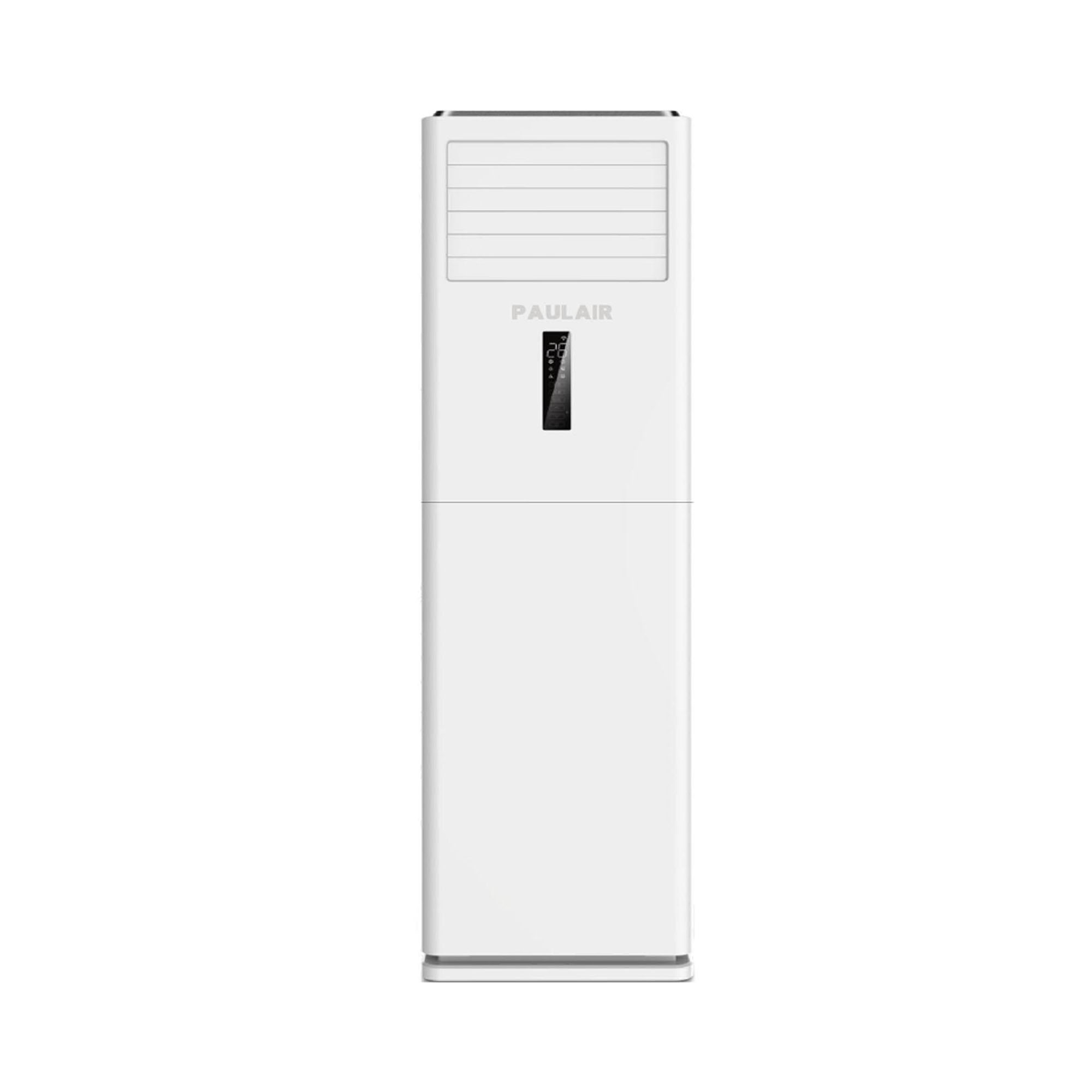
The outer shell of a machine or enclosure rarely comes together by accident. It starts with flat sheets of steel or aluminum, laid out on a layout table where scribe lines and center punch marks decide every bend, notch, and relief cut. A skilled hand reads the grain direction before the first cut, knowing that folding against the grain can crack a panel at the corner. From there the work moves through shears, press brakes, and rolls, each pass nudging the metal closer to a three-dimensional form that will eventually wrap around internal components with almost no visible fasteners.
What separates careful sheet metal work from rushed fabrication shows up in the details you only notice when you run a thumb along an edge. Hems get folded tight enough to feel like solid rod. Weld seams get dressed back and sanded until they disappear under primer. Corner joints are chosen not just for strength but for how water, dust, and vibration will move across the surface over years of use. A well-formed shell doesn't just cover the equipment inside; it gives the whole assembly a quiet rigidity that keeps panels from drumming against each other.
Tolerances here are measured in fractions of a millimeter, but the real test comes during dry fitting. If louvers line up straight, if access doors swing without dragging on their frames, if the finished shell returns a solid thud rather than a tinny rattle when tapped, the forming and joining stages did their job. That level of fit doesn't come from CAD drawings alone. It comes from operators who know how metal springs back after a bend, how heat from welding pulls a panel out of square, and how to compensate with a few hammer blows on a leather sandbag before the part ever sees a paint booth.
Coil Building: Fins, Tubing, and Heat Exchange
Fins rarely get the attention they deserve, but they are the part of the coil that decides whether heat moves into the room or stays trapped in the pipe. A good fin pattern increases surface area without forcing the air to work too hard. That balance matters because tightly packed fins can raise static pressure and reduce airflow, which undermines the very exchange you are trying to improve. On many coils, the fin collar also keeps the tubing firmly seated, so the bond between fin and tube remains a quiet but critical detail.
Tubing choices shape how the coil handles pressure, temperature, and corrosion. Copper is common for its workability and thermal conductivity, but the wall thickness and diameter need to match the refrigerant or fluid conditions, not just the connection size. Long circuit paths can cause pressure drop to creep up, while short paths may leave part of the coil underused. In practice, builders often rearrange the tube circuits to even out the load, especially when a coil runs below full capacity for much of the year.
Heat exchange in a coil is not a single event but a series of small compromises. Air temperature changes as it passes through the rows, which means the first row sees different conditions than the last. Because of that, row-by-row performance can shift more than a basic rating suggests. Builders who pay attention to fin height, tube spacing, and circuit layout together tend to end up with a coil that performs well without needing oversized fans or compressors to compensate for poor internal balance.
The Refrigerant Loop: Brazing, Evacuation, and Charge
Brazing a refrigerant loop rarely forgives rushed work. While the torch flame does the visible joining, what matters just as much is the low-flow nitrogen moving through the tubing during the heat cycle. Without it, copper oxidizes on the inside and those black flakes eventually find their way into expansion valves or compressor reed plates. Heating the fitting evenly, feeding the alloy only when the base metal is hot enough to draw it in, and keeping the joint still until the silver solidifies all separate a reliable seal from a future leak. It is also worth checking the joint under a mirror or borescope if the location is tight, because a shiny shoulder on the outside does not always mean full penetration at the back.
Evacuation is often treated as a timer exercise, but a deep vacuum is about pulling moisture and non-condensables out of places they hide, not just watching a gauge needle drift. The vacuum pump should be connected with large-bore hoses and a micron gauge placed as far from the pump as practical. Pulling below 500 microns, blanking off the pump, and watching for a slow rise tells you more than a fixed thirty-minute ritual ever will. If the pressure climbs and then levels, there is still moisture boiling off; if it keeps rising, there is likely a leak. Letting the system stand under vacuum also gives the oil in the compressor a chance to release water vapor it absorbed while open.
Charging works best when it is treated as a measurement rather than a guess. The factory charge weight remains the primary target, but after that initial fill the real tuning happens at the condenser and evaporator. A digital manifold and a clamp-on thermocouple can show whether the liquid line subcooling and suction line superheat match the system design, and small adjustments are often needed as indoor and outdoor loads shift. Adding refrigerant until the sight glass clears may work on some older systems, but it can easily overcharge a modern high-efficiency unit. Weighing the charge in, then letting the system run long enough to stabilize before making a final trim, usually produces a cleaner start-up than chasing pressures too early.
Mating Indoor and Outdoor Sections on the Line
Getting the indoor and outdoor halves to meet cleanly on the line still comes down to how well the earlier stations held their tolerances. A few millimeters of drift in a wall panel or roof cassette turns what should be a quick drop-in into a fight with pry bars and shims.
The actual mating begins with the gasket and sill details, since those are the surfaces that will take weather once the unit leaves the floor. The outdoor section is brought in on the transfer cart, squared to the indoor frame, and then drawn together with controlled torque rather than pulled by hand.
After the joint closes, the crew checks the interior reveal and the exterior lap before any fasteners are driven. That sequence catches misalignment when it is still cheap to correct, and it keeps the final weather seal from becoming a cosmetic patch job.
Noise, Leak, and Performance Checks Before Shipping
Every unit sits on the bench for a final round that is deliberately boring: run it, measure it, log it, and move on. Air lines are pressurized to 1.5 times the normal working pressure while a digital sensor watches for even a faint decay, so small leaks don't get a chance to become field complaints. Sound readings are taken at idle and under a full simulated load, with the microphone placed where an operator would actually stand rather than in a padded corner of the lab.
Performance gets checked against the same reference curve we have used since the first production batch. Flow, pressure stability, current draw, and outlet temperature all need to land inside a narrow window before the serial number is recorded. If a unit drifts or sounds different from its reference run, it is pulled, reworked, and tested again from scratch.
Only after those numbers are written down and signed off does the unit get cleaned, capped, and packed. The goal is not to inspect quality into the product at the end; it is to catch the rare assembly mistake before a customer ever has to deal with it.
FAQ
The raw stock usually goes through cutting, punching, and bending before it ever reaches the main line. Copper tube is cut to length, deburred, and bent into hairpin shapes, while steel sheets are stamped into panels. Those parts are then moved to subassembly stations where coils are stacked and fins are pressed on.
It is mainly to remove moisture and non-condensable gases from the tubing. If moisture stays inside, it can freeze at the expansion device or form acid with the refrigerant oil. The vacuum also gives the system a chance to prove it is sealed before charging begins.
Most factories use a mix of pressure-decay testing, electronic sniffers, and sometimes helium or nitrogen tracer gas. The circuit is pressurized, held, and monitored for a pressure drop. In areas where a leak would be too small to spot quickly, a sniffer wand is passed around brazed joints and service valves.
It is a split. Stamping, fin pressing, sheet-metal folding, and some welding are highly automated because speed and repeatability matter there. But routing wiring harnesses, making final brazed connections, securing fittings, and checking cosmetic condition still depend heavily on hand work and judgement.
Each unit carries a barcode or QR code tied to its build order. Scanners at stations trigger the correct torque settings, charge weight, and test program. Some stations also use pick-to-light bins and shape-coded connectors so a wrong part or reversed plug becomes obvious before it moves further down the line.
The compressor is usually set into the base pan fairly early because everything else connects to it. It is bolted through rubber isolators to reduce vibration. Its suction and discharge stubs stay capped until the piping is ready to be brazed so dirt and humidity cannot enter the shell.
A finished unit typically goes through a run test in a calorimeter or enthalpy room. The unit runs at rated conditions while sensors check suction and discharge pressures, supply air temperature, power draw, and sometimes sound. Units that fall outside the expected window are pulled aside for diagnosis instead of being packed.
Conclusion
Inside a modern air conditioner factory, assembly begins well before the familiar white cabinet appears. Raw aluminum and copper enter the receiving area and are immediately sorted for the two most demanding jobs: building the outer shell and forming the heat-exchange coil. On the sheet metal line, steel is cut, punched, and folded into panels that must hold motors, compressors, and electronics without rattling. Nearby, fin presses punch thin aluminum strips at high speed while workers feed copper or aluminum tubing through stacked fins. A mechanical expansion tool then swells the tube so it bites firmly against every fin, creating the tight contact needed for efficient heat transfer.
The refrigerant circuit is assembled with stricter controls. Brazing joins copper joints under careful heat, and the closed loop is evacuated to remove moisture before the precise factory charge is added. Indoor and outdoor halves are then paired on the final line, wired, and connected. Every unit passes through noise booths, pressurized leak tests, and live performance runs that compare actual cooling output with the model specification. These checks filter out minor defects before packaging, so the unit that reaches a warehouse or job site already carries proof that it can handle the load it was designed for.
Contact Us
Contact Person: Jack
Email: [email protected]
Tel/WhatsApp: +86-13335127698
Website: https://www.paulair-refrigeration.com